
Revenge is a dish best served cold... and it is very cold in space.... MegaBloks Klingon D7 Battle Cruiser
Ok… so I have to admit that I am a MUCH bigger Star Trek fan than my son is… I was raised watching it so I can’t help it!!! But, that being said, the MegaBloks Enterprise model that we built was just AWESOME, so I couldn’t resist doing the Klingon D7 Battle Cruiser as well. And, I couldn’t do it if we didn’t put lights on it as well, right??? (you’re supposed to agree with me on this one!)
So, I tackled another MegaBlocks build here… as with the Enterprise (my write up of that one is at http://forum.brickstuff.com/t/k9620v/megablocks-uss-enterprise), these present a certain challenge because they fit SO tightly that there is almost no space for wiring to be inserted, much less lights. So, sometimes you have to improvise. But, I’ll leave you all to judge how this one came out.
Let me start by saying that for this model, you HAVE to build it out in reverse order or else you won’t ever get everything tucked in (well you don’t HAVE to but I would strongly recommend it!). All of the wiring and connections are concentrated in one place (that’s the improvised part), so it is definitely easier to work inwards from the wings towards the fuselage when you’re building it. That being said, let’s jump into the build.
So, start with the nacelles first, which are pages 23-29 of the instructions. First on page 24, place two white picos beneath the 2x3 transparent green plate and then run the wiring beneath the decorative plates along the outer face of the wings: (you’ll do this step twice, once for each nacelle)


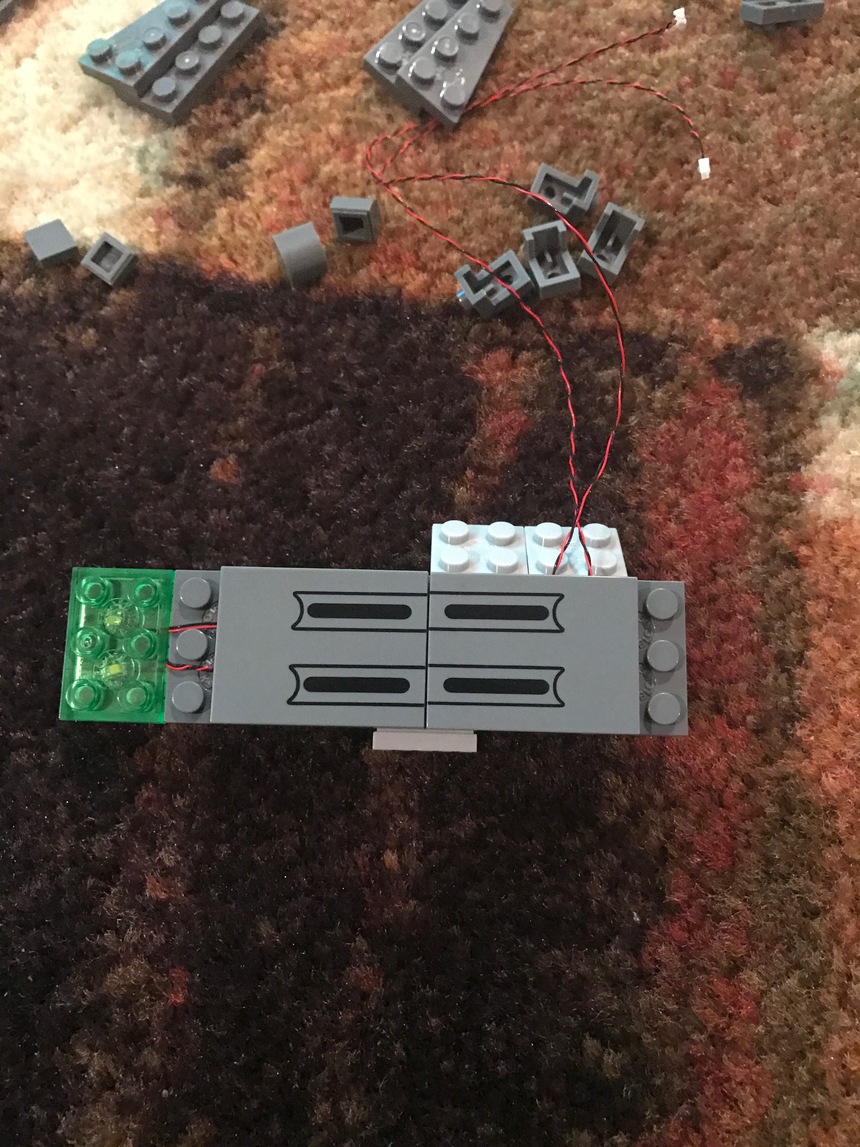
Next, you want to run the lights for the disruptors. I wanted these to have the flickering effect (not just the flashing effect), so they will be wired up to a 2-channel micro lighting effect controller with flickering effect. Therefore, when you’re brining all the wires together, make SURE you have the disruptor wires marked so you know which is which when you’re going to plug them all in.
For these, you’re just using standard white pico lights inserted beneath the green long pieces that come with the set. It’s a tight fit, but they do work correctly.
Now, you go to pages 19-22 of the instructions to assemble the wings and attach the nacelles to each wing. For each side, you’re going to use a flashing white pico and a 1x1 transparent green Lego brick for the running lights (the parts that come with the kit won’t work here).
Then run the wiring from the wings beneath the plates (BE CAREFUL… make sure you run the wires so that they fit in between the studs!) and then bring all of the wiring out from under the plates where the hinges are that attach the wings to the main fuselage assembly:


Now, before you do the main fuselage assembly, complete the stand, using a 24-inch wire to run up one of the legs with about 2 inches of slack at the top end: (for reference, this is pages 4-6 in the instructions)


Now, you’re on to the last part which is the main fuselage (pages 8-15) (I told you this one jumps around!). Starting at step 2, you’ll start laying in the wiring for the impulse drive lights. It’s a little hard to judge just how much slack you’ll have to leave, but basically, you’ll want to leave enough to make certain they can mount where the impulse engine exhaust is going to be placed. Also, you will be replacing the solid piece with two 1x2 transparent red plates.
Once you get to page 13 (step 16), put in two flashing white pico lights underneath the triangular piece with enough slack to mount them later (at step 22); they will be secured with a 1x1 transparent green round Lego brick. You’ll repeat this for both for the forward running lights on each side:


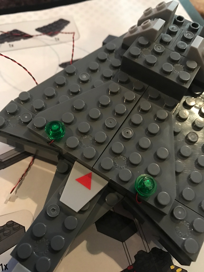


So, when you’ve completed those steps, the assembled fuselage will look something like this:

Now, you’ll snap the wings on and it’s time to improvise! So, I tried a couple of different ways to get a cover box on the bottom of the ship as thin as I could, but there was just too much bulk with the all the connectors and wiring, so I wound up using four 1x2 and two 1x6 Technic bricks to create the enclosure and then three 2x6 and one 2x4 plates to seal the bottom in. The Technic bricks allowed me to run the wiring through the sides of the box cleanly. I wasn’t too happy with the extra bulk it added to the bottom, but it still works:


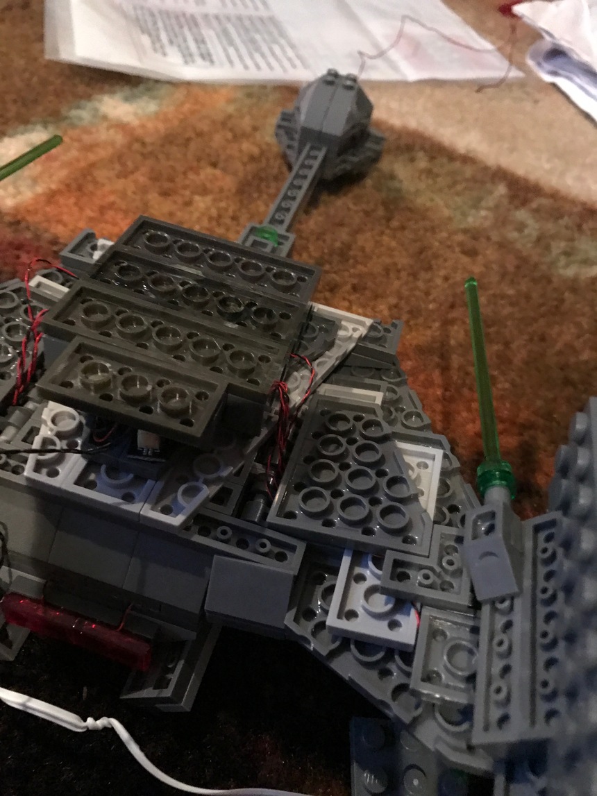
So, the result? I didn’t think it came out too bad. I actually thought it came out pretty good:


You’ll spend a little bit of time with this one if you decide to take it on. For a smaller build, adding the lights adds a good deal of difficulty to the build, but I really was pretty happy with the overall outcome.
As always, questions and comments are more than welcome. Again, a big thanks to Rob for bringing lights to our creations!!!
(my initial notes... not completely accurate, but included here!)
Parts required:
- flashing white picos — 4
- white picos — 8
- 1x4 expansion boards — 3
- 2-channel micro lighting effect controller with flickering effect - 1
- 1.5” extension cables — 3
- 6” extension cables — 3
- 12” extension cable — 1
- 24” extension cable — 1
- USB power cable
- Lego power button
Lego parts:
- 1x2 transparent red plate — 6
- 1x1 transparent green round brick (3006848) — 10 (maybe)
- 1x1 transparent green round plate (3005748) — 20
- 1x2 transparent green plate (4217436) — 20
- medium stone grey plate 2x3 (4211369) — 2
- medium stone grey plate 1x3 (4211429) — 8
Instructions:
- (Page 13 - Step 16) — lay in two flashing white picos underneath triangular piece with enough slack to mount at step 22
- (Page 14 - Step 18) — mount two white picos to the impulse drive; cover them with two 1x2 red transparent Lego plates
- (Page 15 - Step 22) — mount the two flashing white picos beneath the Lego 1x1 green transparent round plates
- (Page 19 - Step 33) — mount a flashing white pico beneath a Lego 1x1 green transparent round brick and run the wire beneath the deck plating with the Klingon logo
- (page 20 - step 39) — (repeat the above step for the other wing)
- (page 24 - step 50) — lay in two white pico lights along the length of the nacelle; place them under the 3x2 transparent green plate (just in case, order 12 1x1 Lego transparent green plates instead)
- (page 25 - step 53) lay in the wiring for the white pico to the lead of the disruptor along the two 2x2 pieces, leaving enough slack to attach the light
- (page 28 - step 60) — (repeat the above step)
- (page 29 - step 63) — lay in the wiring for the white pico to the lead of the disruptor along the two 2x2 pieces, leaving enough slack to attach the light; these two leads will (from the cannons) will attach to the controller for the effects
Build notes: It is best to build this model in reverse due to the fact that all the lights will be connected in one place (basically) and because all of the wiring has to run outward back to a central point. So, build in the following order:
- (1) both nacelles first (pages 23-29) — two lights coming from the back (will join the wires with the wing light) and the one light coming from the front (the front disruptors lights will tie into a single controller)
- (2) wing assemblies (pages 19-22) — run the disruptor light lead separately and the other three leads together under the wing (in between the plates) towards the rear of the wing assembly (make sure you have enough slack for the disruptor light)
- (3) stand (pages 4-6) — attach the power button on the rear corner and run the wire (12” or 24”) up one of the clear support struts for the power feed
- (4) main hull (pages 8-15)
- starting at step two, start running the wires for the impulse drive and the running lights on top of the wings; these will all connect to one 1x4 expansion board; run the wires through the plates as you go upwards in the hull
- after step 14 is completed, build the wire holder to the rear of the dorsal side of the hull assembly (use the two 2x3 plates and the 1x3 plate for the base, use the 1x3 plates for the three sides (two high) and use the last 1x3 plate on the front side to keep the boards in the box); run the feed from the base behind the box (from the rear) and coil the slack from the feeds along with the four boards inside of the box